Definitions:
- Columns and Stanchions: Vertical compression members in buildings.
- Struts: compression members in roof trusses
- Beam: Jib of a crane.
- Beam column: Co beam that is acted on by an axial compressive force in addition to transversely applied loads.
Classification:
- Short Column: A column that fails essentially by direct crushing at ultimate load.
Crushing load Pc = fc.A,
fc=
ultimate crushing stress.
- Long columns:
- Members considerably long in comparison of lateral dimensions.
- The member essentially fails by buckling or crippling to bending.
Radius of gyration:

Slenderness Ratio : Effective length/least radius
of gyration.
Significance:
As slenderness ratio increases, permissible
stress or critical stress reduces, consequently,
load carrying capacity also reduces.
- Radius of gyration will be least along major axis of cross section.
Eg:
for a rectangular column along yy -axis
- For a given area, Tubular section will have maximum radius of gyration.
- H-Section is more efficient than I-Section.


Equilibrium of a column: A column is said to have
buckled or failed when it reaches “Neutral Equilibrium”.

Euler’s Theory:
- Critical load: The smallest force at which a buckled
shape is possible. Prior to this load the column
remains straight. The columns buckle in the
plane of the major axis of the cross section as
shown below:

- Assumptions:

- Column is initially perfectly straight and is axially loaded.
- Section of column is uniform
- The material is perfectly elastic, homogeneous, isotropic and obeys hook’s law.
- Length of column is very large compared to lateral dimension.
- Direct stress is small compared to bending stress corresponding to buckling condition.
- Self weight of column is ignorable.
- The column will fail by buckling alone.
- Euler’s formula for general case: For
a general case critical load,

Where
l=
Effective length
I
= Moment of Inertia of section about the axis of
least resistance.
E
= Young’s Modulus.
- Effective length and critical loads for various boundary conditions compared to a column whose both ends are hinged.
l
= Eff. Length
L
= actual length

- Limitations of Euler’s formula:
- Euler’s formula can also be written as As f and E are constant for a particular material, Euler’s formula is valid for a particular range of slenderness ratio, for e.g. for mild steel whose fc = 3300 Kg/cm2 and E = 2.1 x 10⁶ Kg/cm2 Euler formula is not valid for slenderness ratio less than 80.

- Euler’s formula are valid only up to proportional limit i.e., in linear inelastic zone
Note:
- The relation between slenderness ratio and corresponding critical stress is hyperbolic.
- According to Euler formulas the critical load does not depend upon strength property of material the only material property involved is the elastic modules ‘E’ which physically represents the stiffness characteristics of the material.
Rankine’s formula:
- It is an empirical formula.
- Takes into account both direct crushing (Pa) load
and Euler critical load( PE)

Basic
Formula :

Rankine’s
Co-efficient: is independent of geometry
and end conditions, can be modified to incorporate
imperfections

Material
|
fy
|
Rankine’s
Constant
|
Mild steel
|
3200
|
1/7500
|
Wrough Iron
|
2500
|
1/9000
|
Cast Iron
|
5500
|
1/1600
|
- Rankine’s formula is valid for any type of column.
- No limitations for slenderness ratio.
Straight line formula : (Johnson’s straight line formula)(Empirical)
- It is assumed that allowable stress depends or L/r (slenderness ratio) and varies in a straight line fashion. Applicable to small slenderness ranges
P=A[f-n( λ)]
A = cross sectional area of column
f= allowable stress in column material
n = constant depends on the material
λ=
slenderness ratio


Parabolic formula: (Johnson’s straight line formula) (Empirical)
- Allowable stress is assumed to vary as (L/r)2
P=
A[f - Bλ2]
Where:
P
= safe load on the column
A=
cross sectional area of column
F
= allowable stresses in the column material
λ = slenderness ratio
Eccentrically loaded columns:
- Euler’s formula
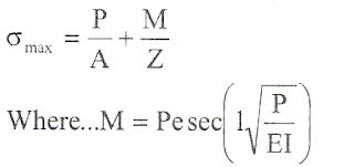

Where
Where σmax = critical stress in the column
P
= axial load on the column
e =
eccentricity of the column load
I = effective length of column
EI=
flexural rigidity
- Rankine’s
method:

P=Rankine’s
load
f=
allowable crushing strength of material
e
= eccentricity of loading
Yc
= distance of compression fibre from centriod
λ = slenderness ratio
r
= least radius of gyration with respect to minor axis
- Secant formula:
For
standard pinned column

σmax =
maximum stress is located at the extreme compression
fiber of the middle point (x = L/2)
of
the column.
Validity:
It applies to column of any length provided
the maximum stress does not exceed
the
elastic limit.
NOTE:
- In the above equation (‘r’ may not be minimum since it is obtained from the value of ‘I’ associated with the axis around which bending occurs.
- The relation between σmax and ‘P’ is not linear σmax increases faster than ‘p’ . Therefore the solutions for maximum stresses in columns caused by different axial forces cannot be super posed instead, the forces must be superposed first, and then the stresses can be calculated.
Perry’s formula: (approximate formula)

Where
σ = permissible stress in the material(given)
From
the above equation ao can be calculated with
that safe load is equal to P = σ0A
σ = maximum permissible stress
σo
= stress due to direct load
σE = stress due to Euler’s critical load
Yc = distance to extreme compression fibre.
Core of a cross section: The area with in which a
direct load to act, so as not to cause tension in any
part of cross section.
- Rectangle or square: Middle third rule Core is
a rhombus whose diagonals are d/3 and b/3
Are of core = bd/18 i.e.,
1/18th of total area.

- >> Solid circular section:

- middle fourth rule
- core dia is d/4 (i.e., eccentricity limit is d/8 to avoid tension) and core area is 1/16th of area of circular section.
- >> Hollow circular section
External
dia = D
Internal
dia = d


